Part V: Remote device access with AWS Serverless and IoT Core technologies and Terraform deployment
Building and evolution of a Raspberry Pi based temperature control system

You can reach all articles of the series using this link.
I have been thinking on what a market viable product would look like, i.e. what technical and product problems shall be addressed to productize the temperature control device.
I plan to write a future article about my ideas, now I want to focus on one key feature: remote device access.
The problem
Currently, the temperature control device can be accessed only through local network, which is a good start, but some kind of remote access would be required for a product. At this point I am not sure whether it would be needed as a minimum feature or as a value-added service available for a subscription fee, I will focus on the technical feasibility.
This article is about creating an architecture design and implementing a prototype for the remote device access.
The traditional way
Some of you with IT admin background might ask what is the difficulty here: we just need to set up a VPN to the temperature control system and problem solved.
Well, we have implemented it for the guest house, but the setup requires lots of work:
need a public IP address: ISPs in Hungary require significant fee for public IP address, even for a dynamic one,
dyndns – or equivalent – subscription to have an easy to remember domain name instead of an IP address,
need a device on the local network – near the temperature control device – being capable of serving VPN,
set up port forwarding to the VPN server – VPN clients must access the VPN server from the public internet,
install and set up VPN client on all mobile devices that want to access the temperature control remotely,
the maintenance and security updates of all the above.
As you see, this is very far from easy for the end user, so I definitely wanted a solution requiring minimal setup for the device and nothing for the end user.
High-level requirements
I put on the hat of an imaginary, just forming, very small company with very limited resources, i.e. if we made the decision to productize the temperature control device.
The goals of such company would be for the remote access infrastructure:
remote access through a public URL,
local and remote access shall use the same UI and API,
simple device onboarding process,
no significant investment for the infrastructure – servers, storage, network, etc. – needed,
cost effective with very small number of devices,
scales well as user base – sold devices – grows,
high availability (HA),
automated deployment and update,
minimal administration work,
isolated devices with high security.
Tool and technology selection
Hosting public web applications and services can be done by renting a bunch of VMs and storage for the app server and database, but the other requirements – no upfront investment, HA, minimal admin work and good scalability – are not easy and quick to do for a small company.
To achieve them, I would use the services of a major Cloud provider and the scaleability and minimal administration are pushing towards Serverless technologies that scale well and the cost depends on the number of onboarded devices.
For a company starting with minimal users that would be the most effective. After reaching a certain size, Serverless might not be the best choice from cost perspective, but it is a long term problem for our imaginary company just starting.
Cloud provider: AWS
My personal preference is AWS with which I have the most experience by far, but Azure or Google Cloud could be a good choice as well.
UI hosting and application data endpoints
The remote UI and AWS backend quickly started to form in my mind based on past experience:
UI storage: S3 bucket
UI hosting: CloudFront distribution with Route53 registered domain
Identity management: Cognito
REST API entry points with authorization: API Gateway with authorizer
REST API endpoint implementations: Lambda functions
Logging: CloudWatch log groups
Database to store sensor and heater values: DynamoDB tables
Infrastructure access control: strict IAM Policies
Device – AWS communication
The device – AWS database communication was not so clear for me, I knew few possible messaging services but I wanted to discover the possibilities before making any decision.
Available services
I checked the AWS messaging page for the possible services and found some I had no experience with. The options listed are:
Amazon MQ: a managed ActiveMQ broker, for ActiveMQ users to migrate to,
Amazon SQS: Highly scaleable message queue for distributed systems and serverless applications,
Amazon SNS: pub-sub messaging and mobile notification with high throughput,
Amazon Pinpoint: Customer engagement platform,
Amazon Kinesis Streams: highly scalable and real-time data streams,
AWS IoT Message Broker: high throughput, managed pub-sub broker service integrated with AWS IoT Core, targeting devices.
Finding the right one
I had experience with AWS MQ, SQS and SNS and was also familiar with the capabilities of Kinesis Streams. Pinpoint and IoT Message Broker were new to me, so I checked the use cases, available APIs and some code samples.
As mentioned above, full device isolation and minimal administration are part of my goals. We need a design where the device from/to cloud channels are fully isolated, i.e. each device has its dedicated channels – topics.
On the other hand, I do not want to add new topics to the AWS backend for each new device added, so we need automatically created topics.
In addition, storing the data sent by the device in DynamoDB shall be as simple as possible, i.e. preferably not requiring additional services, like lambdas.
These requirements filtered out MQ, SQS, SNS and Kinesis Streams. The Pinpoint service is for a different use case, let us have a closer look on IoT Message Broker.
IoT Message Broker with MQTT
When I first looked at its name, I had the feeling that this is what we need, but wanted to understand the service and experiment with it.
The IoT Message Broker supports MQTT – Message Queue Telemetry Transport –, HTTP and WebSocket communication and designed for a large number of devices to communicate with AWS backend and IoT services.
MQTT is exactly what we need: a simple queue protocol to send / receive data asynchronously.
Device side
Our devices shall be able to send to and receive data from MQTT topics and an easy way to authenticate the device and grant permissions.
IoT Message Broker provides it, the device onboard consists of the following steps:
Get the AWS IoT endpoint,
Create an IoT thing, practically a representation for our device,
Create a certificate and private key for our device – these are necessary for the device to connect to the AWS IoT Core,
Create a IAM Policy that grants the permissions for the device topics,
Attach the policy to the thing in AWS IoT Core, practically granting it permissions
With these configuration and data and the AWS IoT CA Cert file – which has to be downloaded manually – a device can connect to AWS IoT Core and can send / receive messages.
AWS side
On the AWS side, AWS IoT Core services can be used to receive and send data from / to the device. As sending is simple – need an IAM Policy to grant permission for the Lambda to send to the topic –, I focus on the receiving part.
AWS IoT Core has a clever service, called IoT Rule: you can simply write a script to declare what to do with the data received, like modifying it, storing at S3 or DynamoDB, send through SQS or SNS, passing to a Lambda function and many others.
My first idea was to pass it to a Lambda function which can store to DynamoDB, but there is a direct DynamoDB write capability.
Deployment automation
However DevOps is not my primary area, I have to fully understand, review and sometime modify the DevOps pipeline for my projects. Building something with Terraform has been one of my learning goals for a while.
This prototype development is a perfect opportunity for it: besides designing the architecture using AWS services I needed a way to implement and quickly deploy / modify it.
Designing the AWS infrastructure
Remote UI
To focus on the architecture design and deployment, I did not want to create a new UI or introduce any new feature for it, just wanted to add AWS access. For this reason, I decided to keep the very same UI behavior: the UI and the backend APIs are the same, only the services used and the configuration are different.
The differences to the local UI are:
The UI is downloaded from AWS, instead of the device,
A different service endpoint is used for authentication,
Different service endpoints and authorization method are used to call the APIs,
Log viewer is not available in the remote UI,
The AWS backend acts as a data and command relay: returns the data sent by the devices and forwards the commands to the appropriate device, see below.
Device – AWS connectivity
As the primary use case for the devices are local access, they are the source of truth: they own the data, the AWS backend only provides an interface for remote access. This means that the controls – change temperature and heater state – have to be interpreted and done by the controlled device.
This makes the communication between the device and AWS simple:
AWS sends commands – sent by the remote client – to the device, where it is validated and executed,
The device sends its new state to AWS backend, where it is stored.
The AWS IoT Message Broker service is used for the communication and the device to AWS – uplink – and AWS to device – downlink – channels are implemented by separate MQTT topics, see below in the implementation part.
Architecture design
I came up with the following architecture design for the remote device access.
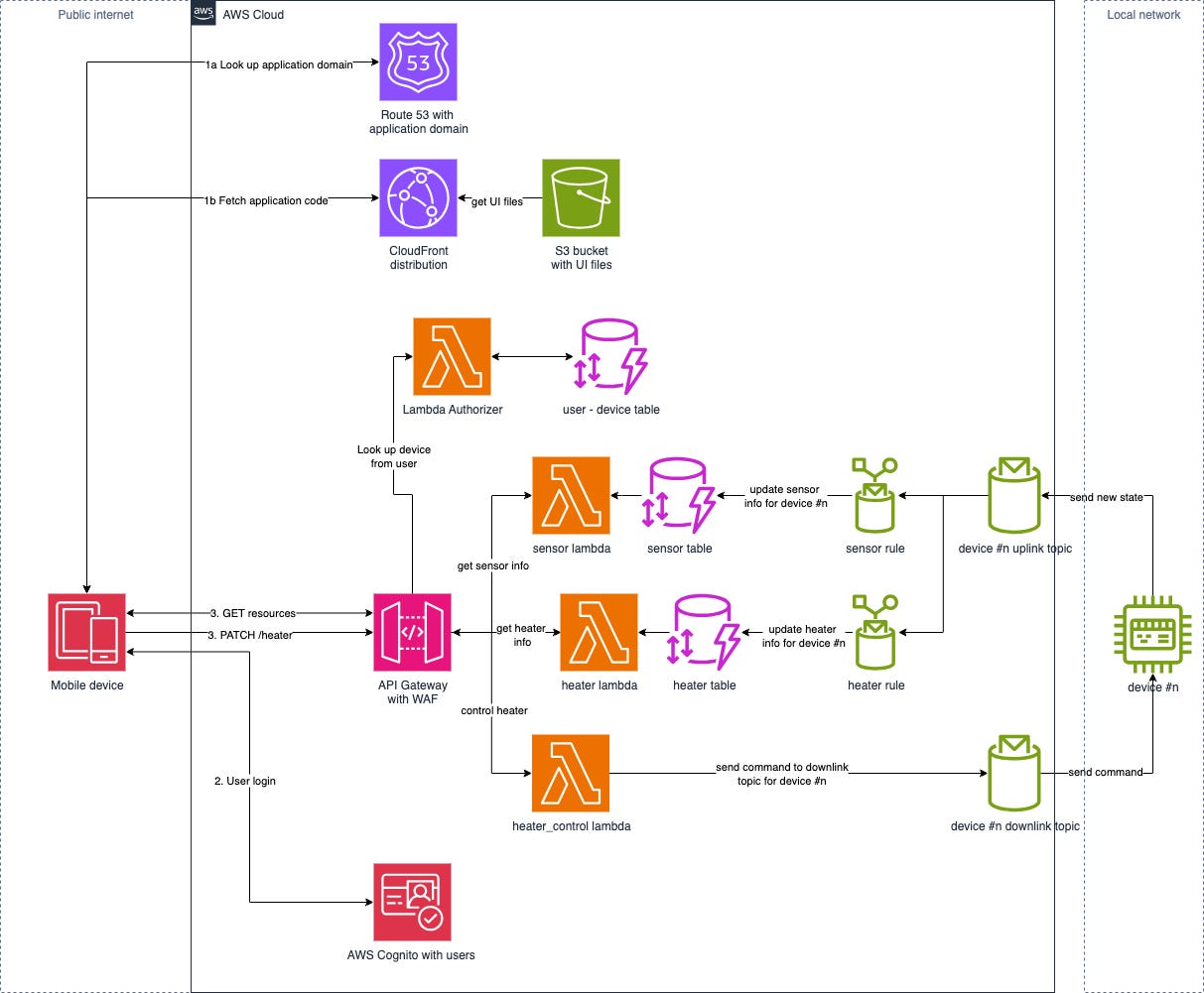
Implementation
For simplicity and fitting in the free tier AWS account, I chose to skip the following part of the architecture design at the prototype stage:
No Route 53 used, no custom domain.
No CloudFront used, UI is hosted from a public S3 bucket website with http:// URL, not https:// – this is a limitation for the public S3 bucket websites, but for the prototype it is sufficient.
No Lambda Authorizer and user – device database are used, the device ID is passed as a hardcoded variable to the Lambda functions – simulating the result of a database lookup. This limits the prototype to one controlled device.
No WAF – Web Application Firewall – is used.
Besides these simplifications, I decided to work on small increments: after each phase I had something testable while I was learning Terraform.
I chose the following increments:
API Gateway + the 3 Lambda functions for the URLs with hardcoded JSON values returned and updates silently ignored: testable with CURL or Postman.
Modified UI – external configuration values + S3 hosting: browser can run the UI and it has the basic functions.
Cognito with users added, AWS specific login on the UI, authorized API Gateway endpoints: login and authentication works, authorized API endpoints.
DynamoDB tables added with pre-filled data: no new functionalities, only preparation for the next phase.
AWS IoT features part #1: the device sends new states through AWS IoT services, states are stored in the DynamoDB tables: locally made changes are showing up in the remote UI.
AWS IoT features part #2: the changes – target temperature, switch heater on/off – are sent to the device: remote control is fully functional.
AWS infrastructure
After creating a new AWS account, I started to add the AWS backend parts to the project. As the above phases are straightforward, I only mention few parts of the implementation.
Lambda functions
From the supported environments, I chose Node.js 20 as the runtime environment, which has the AWS SDK for Javascript v3 available for the scripts.
The examples in the AWS IoT Core page are not very good and were using v2 of the API. I run an unexpected problem while implementing the heater_control lambda function. Besides having to pack the v2 SDK files in the lambda, its execution was too fast for the – async – MQTT handling code and the Lambda function returned before the message was put on the MQTT topic. Switching to the IoT SDK available in the v3 AWS SDK solved the problem, it has functions for message sending supporting await.
DynamoDB
There is nothing special here, I used the device IDs – UUIDv4 – as key and stored a JSON object with the sensor / heated data, simply returned through the REST API.
At early stage of the development I used pre-populated database, for which Terraform has an easy way to do.
API Gateway
There are only few small things to mention here:
CORS has to be enabled as the origin – S3 UI bucket URL – is different than the APIGW URL.
API GW Authorizer had to be configured, its Cognito integration is seamless.
REST API integration had to be done for all endpoints.
CloudWatch log groups
CloudWatch log groups were used for all the Lambdas and the API Gateway.
AWS IoT MQTT topics
For data isolation purposes, all the devices have their own private uplink and downlink MQTT topics: ‘device/<Device ID>/uplink’ and ‘device/<Device ID>/downlink’.
For the prototype, the devices send the whole sensor and heater state to AWS, not only the delta, so there is no need for processing, only the message parts – sensor_data and heater_data – have to be stored to the stored DynamoDB table.
{
  “sensor_data”: [
    {
      “id”: “ROOM01”,
      “temp”: 28.2,
      “description”: “Room name”,
      “validity”: “valid”,
      “humidity”: “60”
    },
    ...
  ],
  “heater_data”: {
    “heaterMode”: “heating”,
    “heaterOperation”: 0,
    “heaterData”: [
      {
      “id”: “ROOM01”,
      “targetTemp”: 20.5,
      “hardState”: “on”,
      “currentState”: “off”
      },
      ...
    ],
    “heaterSchedule”: {
    ...
    },
    “heaterMaintenance”: {
    ...
    },
    “heaterDelayedStart”: {
      ..
    }
  }
}
AWS IoT Core rules
Due to the rule flexibility, generic rules can be written to handle all data sent by the devices at a single location and there is no need for device onboarding here.
The rule itself can be written in a SQL-like language, the following Terraform code creates an IoT rule to write the sensor part of the data received to the sensor DynamoDB table.
#
# IoT Rules for receiving Sensor info
#
resource “aws_iot_topic_rule” “iot_device_rule_sensor” {
  name = “iot_device_rule_sensor”
  description = “Rule to store sensor data sent by device”
  enabled = true
  sql = “SELECT sensor_data FROM ‘device/+/uplink’”
  sql_version = “2016-03-23”

  dynamodb {
    hash_key_field = “DeviceID”
    hash_key_type = “STRING”
    hash_key_value = “$${topic(2)}”
    role_arn = aws_iam_role.iot_rule_role.arn
    table_name = aws_dynamodb_table.sensor.name
  }
}
Please note the ‘device/+/uplink’ and ‘hash_key_value = “$${topic(2)}”’ parts, the magic happens there. The first will execute the rule on all device uplink topics and the last uses the 2nd part of the topic name – Device ID – as the DynamoDB hash key, the sensor_data part of the sent JSON object will be stored.
IAM Policies
Each AWS Service used is assigned an IAM Policy with the minimum necessary permissions for the exact resource it has to call. The only place I granted permission for more resources is the heater_control lambda which has to send messages for all the devices.
Remote frontend (AWS)
As mentioned above, I want to use the same UI for both the device and AWS, so some extra configuration was needed to support multiple modes:
Build-time configuration
I wanted the device and AWS frontend packages built separately, so needed a new option in the environment configuration: modeAWSBackend is set to true for the AWS mode and to false for device mode; also new environments were added for AWS mode: development and production.
Runtime configuration
The project needed some values to be configurable after package build:
API Gateway URL,
Cognito URL,
Cognito Client ID.
Finding the keys in the built package and changing the values are theoretically possible, but is a very bad hack and may change between builds / Angular versions. I wanted a way to read a configuration file from the server using HTTP GET.
I used an injectable Service class to fetch the runtime config file during initialization.
Login process
The already existing login component of the app was used for AWS mode instead of the one provided by Cognito, so it needed few modifications.
To implement the AWS login, I simply assembled HTTP POST call, sent it to the Cognito URL and stored the tokens sent back by AWS, the Cognito documentation was very descriptive.
Calling endpoints
The only modification I had to make for the AWS mode is to include the Access Token in the HTTP headers instead of the headers needed by the cookie-based authentication.
Access token renewal was not implemented in the prototype.
Device backend
As the primary operation of the heater control is the device and remote control through AWS is an extra, only a few modifications were needed:
Configuration item to enable AWS connectivity,
AWS IoT configuration,
AWS connector module,
Send the new states to AWS.
AWS IoT configuration
The following AWS IoT related configuration has to be specified:
Certificate and private key files: generated during device onboarding, this will authenticate the device and let it communicate with the AWS IoT services,
AWS CA cert file: needed for initializing the AWS IoT communication, has to be obtained from the AWS IoT page,
AWS IoT endpoint: endpoint for the given AWS region,
Device ID: name of the IoT device in AWS, used in topic names.
AWS connector module
This module connects the device with the AWS IoT Core. It has the following parts:
Initialization
During initialization, the communication with AWS IoT Core is established – i.e. mTLS communication is set up to the AWS IoT Core endpoint –, MQTT Client is started and subscription to the downlink topic is performed.
Receive command from AWS
When receiving data from the downlink topic – after decoding the JSON –, the relevant part (resource and command) are passed to the same function as used for the REST endpoints. That function performs the data validation.
Status updates to AWS
This function simply assemblies a JSON structure from the current sensor and heater data and publishes to the uplink topic.
Deployment and onboarding
Deployment of the AWS services
The AWS infrastructure is deployed with Terraform, which I had no experience with. After reading the Terraform AWS tutorial it was clear that it provides a one-to-one wrapper on the AWS resources, so once I had the architecture in mind I just had to describe it.
Using the phased approach was a good decision as I had a working system deployed into AWS after each phase. As usual, the first steps – S3 bucket, API GW, lambdas, policies – took significant time – about 2 days if I recall correctly –, but going forward and adding more stuff while learning Terraform was quicker and quicker.
Sometimes it was easier to add the new infra services to the Terraform scripts and re-deploy than try it out manually from the AWS console.
The Terraform file describing the whole AWS side infrastructure was around 800 lines and 48 AWS resources were created, as the below execution shows.
$ terraform apply
...
# random_pet.lambda_bucket_name will be created
+ resource “random_pet” “lambda_bucket_name” {
+ id = (known after apply)
+ length = 4
+ prefix = “tempmgt-function-bucket”
+ separator = “-”
}
Plan: 48 to add, 0 to change, 0 to destroy.
Changes to Outputs:
+ apigw_base_url = (known after apply)
+ cognito_client_id = (known after apply)
+ cognito_endpoint = (known after apply)
+ cognito_user_pool_id = (known after apply)
+ frontend_bucket = (known after apply)
+ frontend_config = (known after apply)
+ frontend_url = (known after apply)
Do you want to perform these actions?
Terraform will perform the actions described above.
Only ‘yes’ will be accepted to approve.
Enter a value: yes
...
aws_iam_role_policy_attachment.lambda_policy_heater: Creating...
aws_iam_role_policy_attachment.lambda_policy_heater: Creation complete after 0s [id=iam_role_call_lambda_heater-XXXXXXXX]
Apply complete! Resources: 48 added, 0 changed, 0 destroyed.
Outputs:
apigw_base_url = “https://XXXXXXXXX.execute-api.eu-west-1.amazonaws.com/tempmgt”
cognito_client_id = “46adej1buh7b6vXXXXXXXXXXXX”
cognito_endpoint = “cognito-idp.eu-west-1.amazonaws.com/eu-west-1_XXXXXXXX”
cognito_user_pool_id = “eu-west-1_XXXXXXXX”
frontend_bucket = “tempmgt-frontend-bucket-strictly-immensely-delicate-XXXXX”
frontend_config = “{\”cognitoClientID\”:\”46adej1buh7b6vXXXXXXXXXXXX\”,\”cognitoURL\”:\”https://cognito-idp.eu-west-1.amazonaws.com/eu-west-1_XXXXXXXX\”,\”gatewayURL\”:\”https://XXXXXXXXX.execute-api.eu-west-1.amazonaws.com/tempmgt\”}”
frontend_url = “http://tempmgt-frontend-bucket-strictly-immensely-delicate-XXXXX.s3-website-eu-west-1.amazonaws.com”
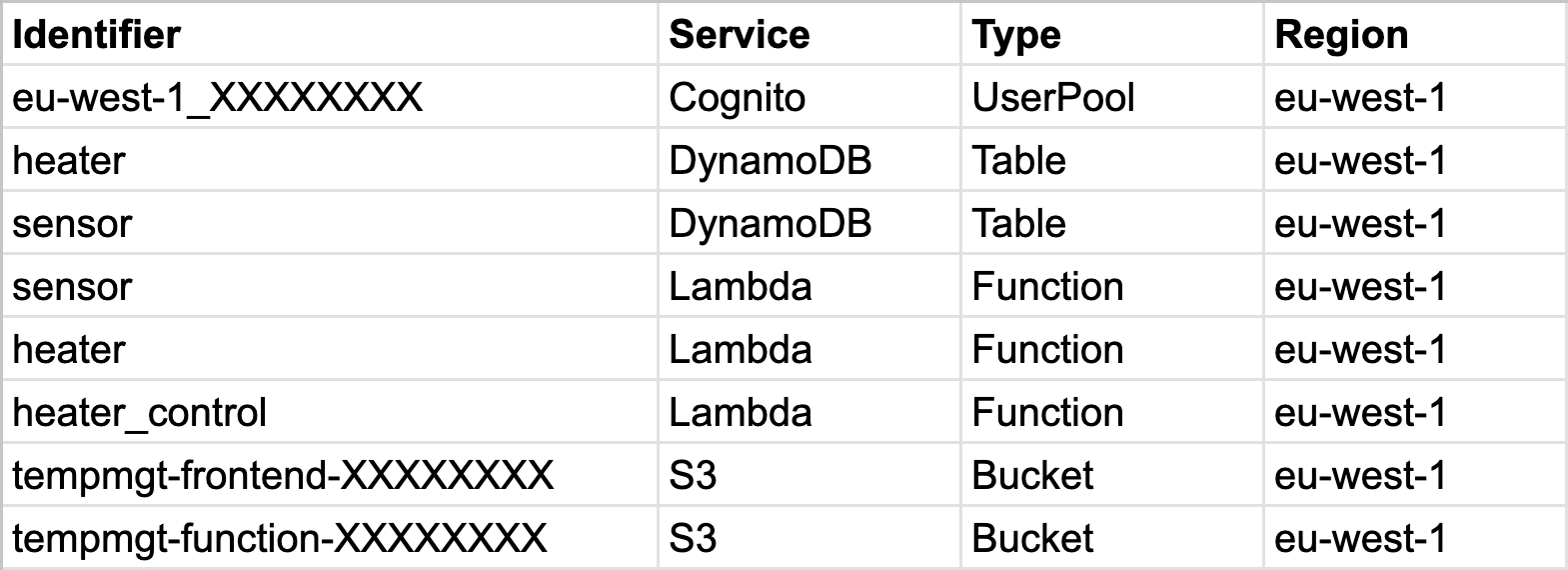
$The whole deployment takes less than a minute and the following services were created:
AWS frontend deployment
During the AWS deployment an empty S3 bucket is created to host the frontend.
The frontend deployment has the following steps:
Query the frontend bucket, URL and configuration from the Terraform outputs,
Copy the frontend config to the assets/ directory of frontend package – the UI will load it as the runtime configuration,
Call an aws s3 sync command to upload the UI to the S3 bucket.
Device and user onboarding
For this prototype I have not developed any user friendly web UI to onboard the devices and users, I used shell scripts calling the aws command.
Creating a device
AWS IoT has the concept of Thing to represent a device. The following detailed steps are done while onboarding it:
Query the AWS IoT endpoint – needed for the device to AWS IoT communication,
Create a Thing,
Create certificate / private key for the Thing,
Create a policy file granting the Thing permissions for the necessary queue operations,
Create a policy with the policy file,
Attach the policy to a principal,
Attach the principal to the Thing,
Assembly the configuration file for the device.
At this point the device is onboarded to AWS IoT Core and with the necessary files – config file, key / cert –, it is able to send / receive messages to / from its queue topics.
Adding a user
Adding the user to the Cognito user pool is straightforward:
Query Cognito specific data from the Terraform outputs,
Add the user and set its password:
aws cognito-idp admin-create-user ...
aws cognito-idp admin-set-user-password ...
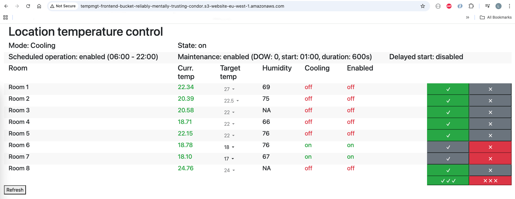
Testing and evaluation
After having all build blocks tested separately, I tested the whole system with the device code running on my desktop.
You might wonder why I have not tested it on the real device: currently I have only one device, which is controlling the heating in my house. I did not want to experiment with a prototype during the last month of autumn.
I am currently waiting for all the hardware parts to arrive for a new device on which I can test some hardware and software modifications as well, will test the AWS remote access on it once it gets assembled.
After all, remote control through AWS worked surprisingly well and fast.
When the UI is running on the device, the state is queried from the device right after sending a command. I was expecting that for the AWS hosted UI I have to add some delay before the state query due to the messaging delay – AWS sends command to device, device sends update to AWS -, but the UI was working well without adding any delays.
I am very satisfied with the prototype and looking forward to test on a real device.
Improvement opportunities
Deployment
For simplicity, everything is deployed in one step now, which means losing the user database when the project is deleted.
In a real product I definitely would separate the Cognito from the other parts of the system.
Cost
During the prototype development I have found several areas where the initial Architecture design was not optimal for Cloud. Once we use Cloud, everything has a cost. Even seeming negligeable, it adds up and optimizing means less cost:
Too frequent UI – backend communication: as the communication is almost costless for the local network, I chose 2 minute as the device cycle and 30s UI – device communication. Due to heating / cooling is a slow process, we can use longer value, like 5 minutes for the device cycle and for the UI – device communication as well to decrease the called Cloud services without significant impact.
2 separate calls for sensor and heater data fetch: on the device I wanted to separate these resources when fetching, but after all they got merged on the UI before display. With merging them the number of fetching UI – AWS calls can be decreased by 50%. Merging the data in the DynamoDB side would eliminate one of the tables and one of the IoT Rules as well.
Moreover, the sensor and heater data are just put in AWS in DynamoDB tables for the fetch Lambda functions to grab them. With this use case, there is no reason for using DynamoDB, object in a S3 bucket could do the same, MUCH cheaper and without the problem of scaling readers / writers. Eliminating 2 DynamoDB tables would be a real cost killer.
Although not implemented, the DynamoDB table to have the user – device mapping might be eliminated as well.
The users in the Cognito user pool can contain the Device ID as a claim and the Lambda authorizer could look up from the JWT token instead of calling an external service.
Of course it would have some limitations compared to a DynamoDB table – access tokens could carry outdated device associations, users would require to re-login -, so an evaluation is needed here.
Conclusion
I am very happy with the prototype and achieved my goals:
improved my pet project,
created a concept and a PoC for a real problem which I might face later: remote device access,
refreshed my AWS knowledge,
got hands-on experience with AWS IoT Core, with which I had not worked with yet,
learned the basics of Terraform and used it for a small, but real example,
Of course this is only a prototype and a real product would require re-evaluating technology selections – HTTP/REST communication – and some new features – show the last update from the device – at minimum to be more user friendly and cost effective.
Next steps
I have few topics in mind about which I want to organize my thoughts and continue the series:
Retrospective: the first version of the temperature control device was deployed about 8 years ago. There were lots of development since then and the original decisions I made are not always matching with what the system has become or simple are not optimal. I need to look back to my past decisions and evaluate them, together with new the hardware possibilities.
I enjoyed digging into and prototyping a small part of the “what a market viable product would look like” question. There are LOTS of technical problems and challenges to be solved to create a product from the temperature control device. I plan to investigate the topic in high level and create some kind of list of technical problems to solve.